This week was we had to try out as many design software as possible, the goal of this week is to fix up a software for which willbe used further throughout the fabacademy.
Also Design, Render,Animate and Simulatation of our final project is the goal of this assignment
I tried my hands with some 2d designing softwares,usually there are two types of 2d designing softwares Raster designing and Vector designing
The difference between vector and raster graphics is that raster graphics are composed of pixels, while vector graphics are composed of paths. A raster graphic, such as a gif or jpeg, is an array of pixels of various colors, which together form an image.
So basically it means that if you zoom into an image made in a Raster Software it is going to pixallate, this is not the case with the vector softwares, they maintain the quality of the image even if you zoom in.
1st Part- Raster softwares-Adobe Photoshop
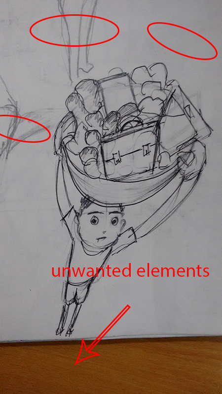
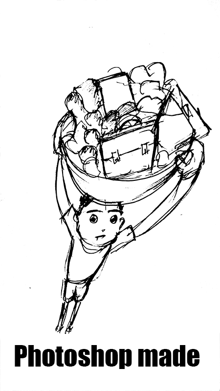
For my Final project I am doing a lot of hand skectching and ideation on paper,the images and the paper itself becomes smudgy and dirty and when you upload it on the web it looks very dull and rough. I wanted to make these sketch cleaner and give it more sketch feeling. I followed some video tutorials on youtube and learnt it.
I did the following It is easy to do and I recommend this for all, the final images have a sketch effect.
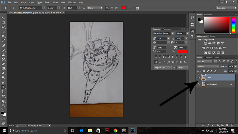
Step 1) Import the image in Photoshop- for this you just drag and drop the image in photoshop.
Step 2)Make a copy of it- Press ctrl+J
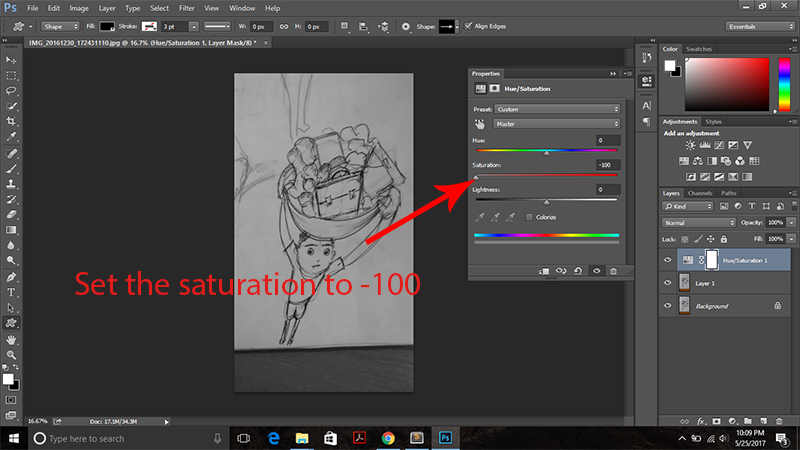
Step 3)Reduce the hue saturation -click he globe icon on the bottom right corner and reduce the hue saturation to -100, the picture will start to look black and white this time
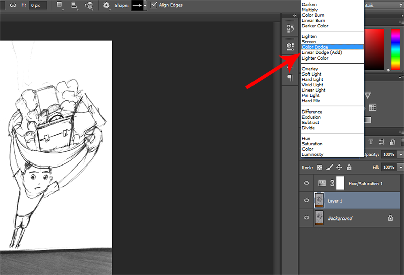
Step 4) Change the blend mode to color dodge- picture is self explanotory, remember to make the image as the active layer and not the hue/saturation level
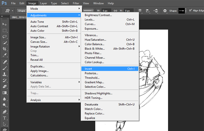
Step 5)Invert it- Press ctrl+J, the picture should appeat totally white this time
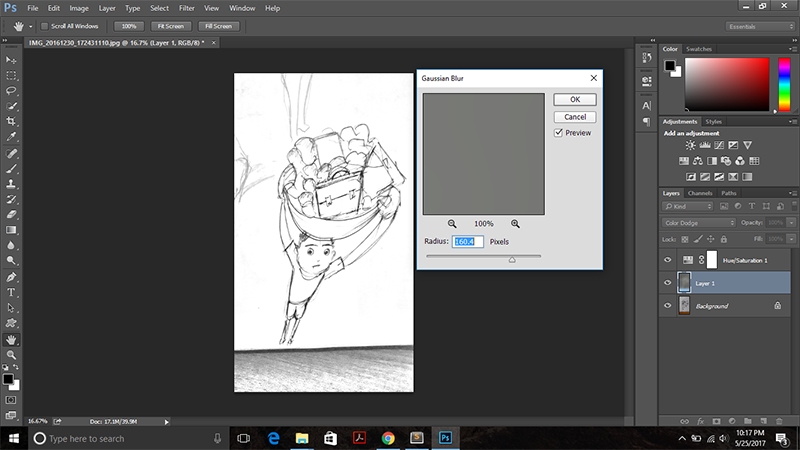
Step 6)Adjust the image- Press filter-blusr-gausian blur, tweak the slider till according to the choice
Step 7)Adjust the levels - Press the globe icon again and choose "levels". Bring the black slider toward the right till the picture gives a sketch effect.
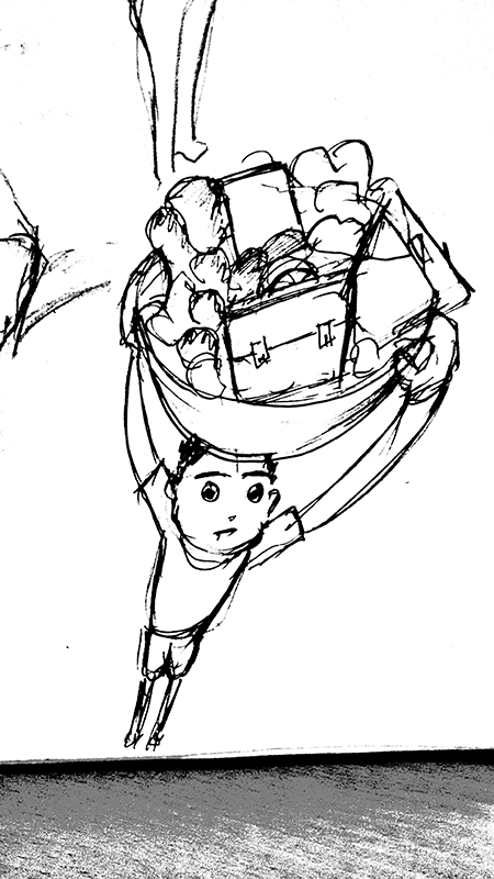
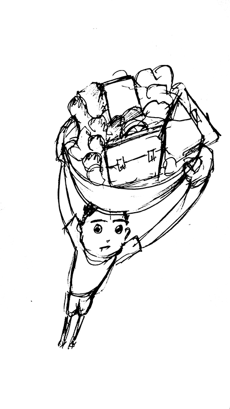
Step 8) Time to clean up - To do this make a composite snap shot by pressing ctrl+shift+alt+E, select a tool brush of required size and opacity 100%, ensure that the foreground is white in the bottom left corner and paint on the unwanted parts. This works like a eraser.
Image before and after the cleaning
Step 9)Now it is just a matter of changing the size of the image by clicking ctrl+alt+I, remember this will reduce the pixel density of the image, if you zoom in too much the picture will appear blur and pixalated, I usually keep my pictures at 800*450px for landscape images and 450*800px fr portrait images
Neil is a big fan of Inkscape, he spoke a lot about it in the lecture especially about the clone function in Inkscape, thus I decided to give it a try, I am not makng anything in it as such, I am jsut going through it, trying out some of its funtions, if I like it I will definitely start using it.
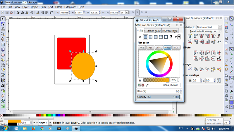
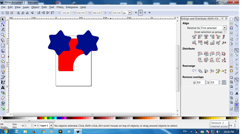
Inkscape has basic shapes in its library on the left had side, there is cicle, triangle, rectangle and polygons whose sides can be increased or decreased as one wish.
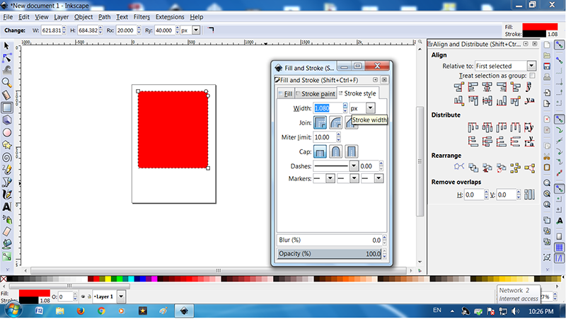
I tried some basic shapes and changed their colours from the stroke and filltab on the top right corner
We also have the ooption to change the colour of the stroke and fill if we want.
I found the layout of Inkscape was self explanatory, everything was visible and handy
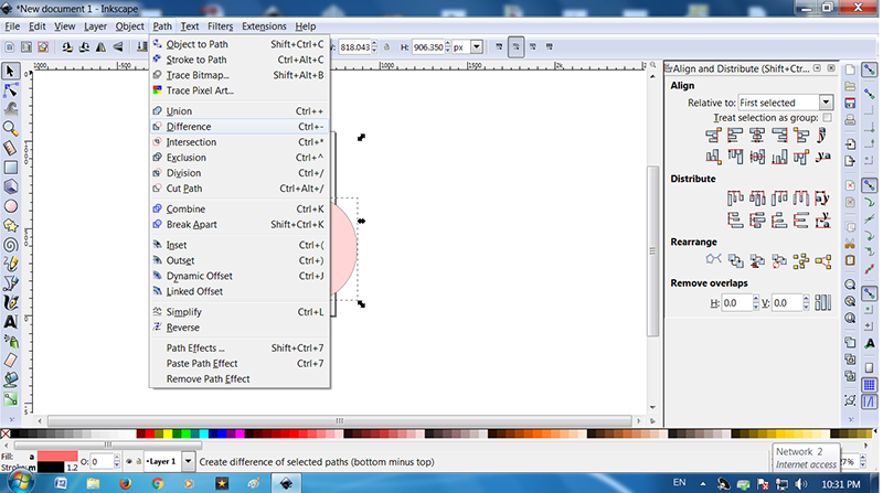
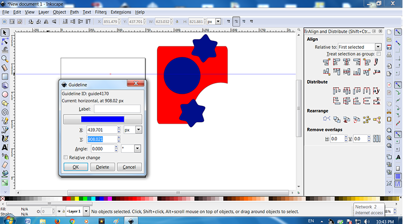
One of the great thing that I found in Inkscape was that it can do Boolean Operations, this is an amazing feature if we want to do something by a subractive or additive method. The figure is self explanatory.
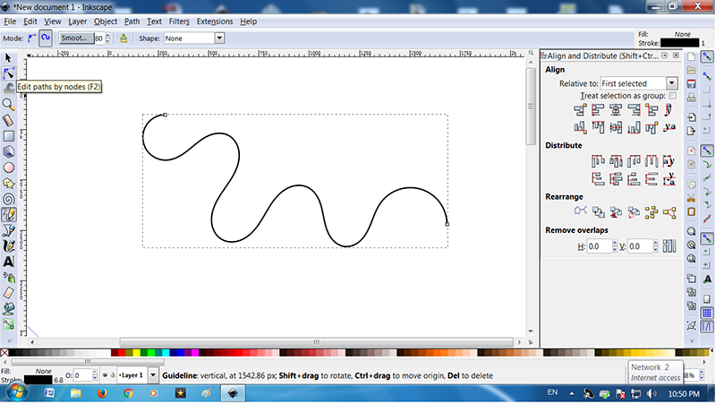
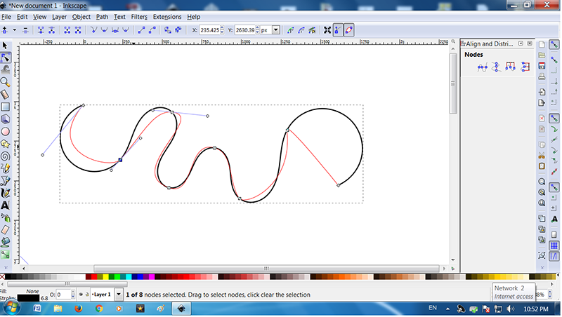
Another amazing tool I found on Inkscape was the Pen tool which has node adjutment, usually the pen tool is used to draw curves in the drawing, but there are not a lot of software which can edit the curves accurately. In Inskscape after you draw a curve and you left click on the curve the nodes get activated, we can adjust each and every corner of the curve,we can make it sharp or smooth as we wish
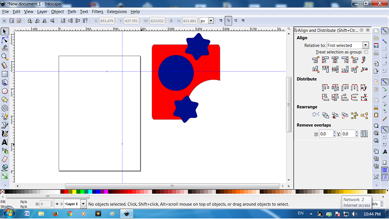
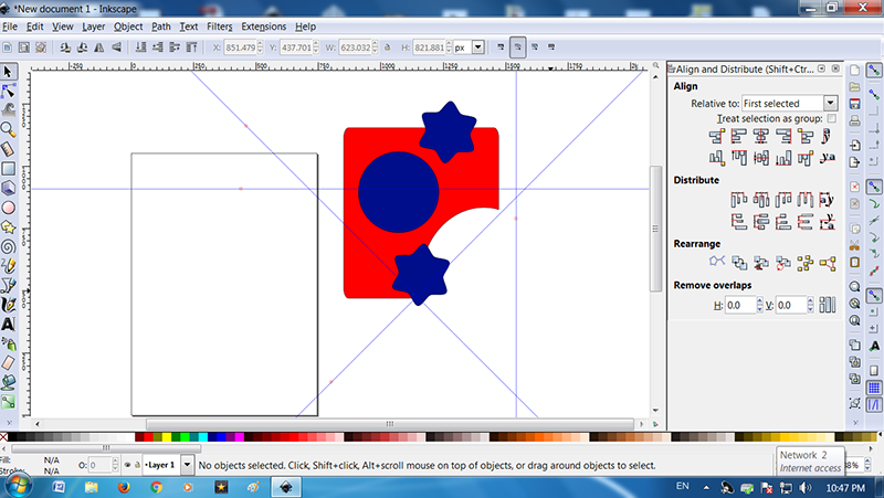
Here is a feature which exists in almost all the 2d designing softwareGuides justdrag the guides on the top or the left of the screen and place it on the canvas wherever you want. This comes handy as it acts like a constrain thus making our drawings accurate.
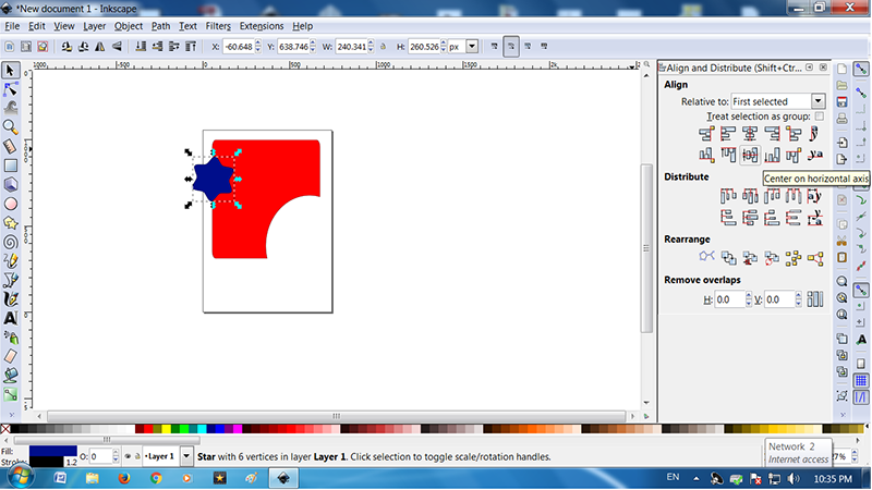
And now Neil's favourite function clone, We can finf it in the edit tab, what is does basically is that it makes copy of the object which not only the visual copy but also a functional replicator of the parent object, thus when you change the size of the parent object its copy does too, this is an amazing feature.
I also tried the align feature in the right side of the window, it has the option to align the object to the center, left or right and so many other options.
All in all, I really happy with Inkscape
Autodesk Autocad
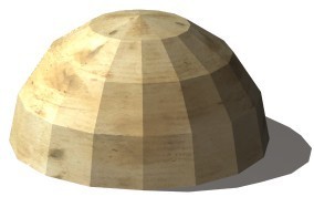
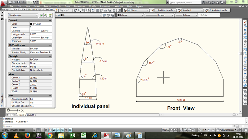
For this exercise I decided to replicate whatever sketchwork I had done in a more precise format. My dome was taking shape on paper and I wanted to do a few detailed drawings of the same. I found an image of a trapezoidal dome on the internet.
I have used Autocad before it is very technical software which uses a lot of constrains and intelligence to create detailled drawings,Although I knew AutoCad falls back in 3d modelling I decided to give it a try for 2d drafting, god thing about it is that it is Vector Software
After deciding the diameter of my dome it was just a question of finding the remaining parameters. I used an online Dome calculator I got the values and started with drafting.
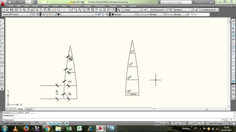
I designed an individual panel of the dome, these panels will be repated 16 times to form a dome.
Here I used some simple line commands, I trimed the extra portion with the trim tool and I used the Copy command to copy the same object again.
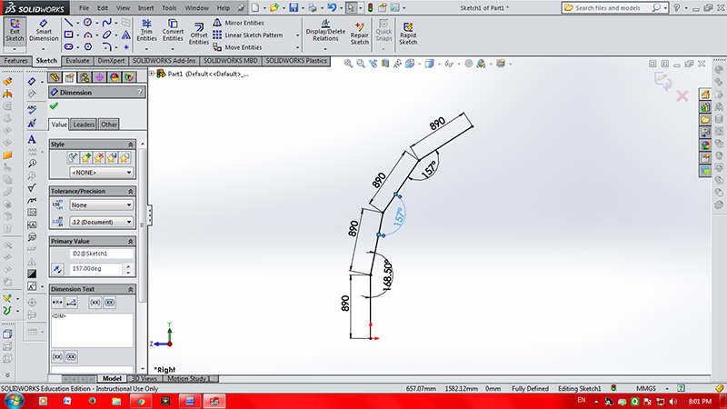
I made the side view of the dome using the similar commands, the software is not exactly parametric, but it has a lot of command on the dimensions, there are a lot of constrains we can specify using the dimensions, here I used the angular dimensions for the side view.
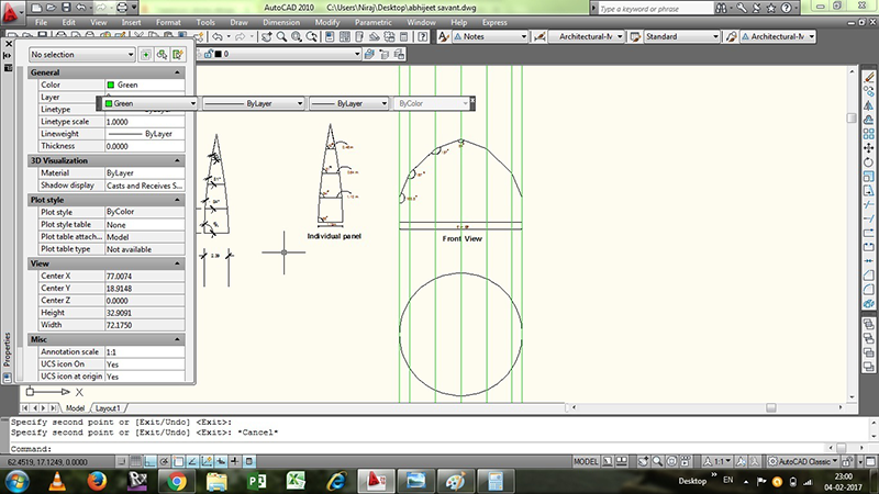
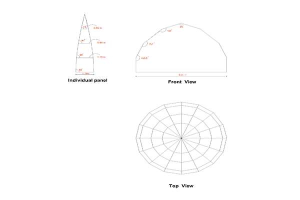
I did the plan view by placing the front view and using rays to plot the lines, this is exactly the same way the paln view is done in the traditional way of drawing on the sheet
I used the circular mirror command to divide the circle into 16 parts and then completed the top view using simple line commands
AutoCad is very precise when it comes to dimensions, I wanted a software which is great with 2d as well as 3d unfortunately AutoCad is not great with 3d designing.
Learning to design in 3D
I have have a little experience with 3 d designing in Solidworks I like that software a lot but I dont want to be biased about it thus I decided to give a try to some other programs Neil suggested
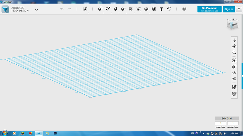
Autodesk 123D Design
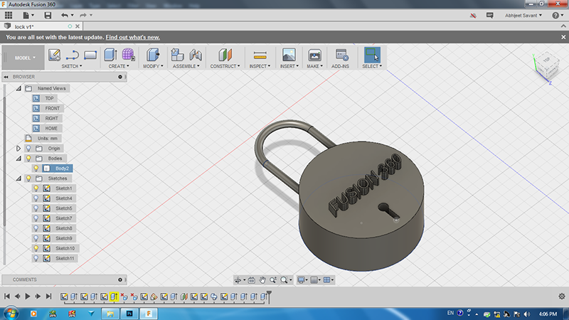
I wanted to make a design of a circular lock, something like this.
I downladed the software and opened it, I am not use to a layout, the plane is in 3d and there is no assisting toolbar on the sides, anyways I started.
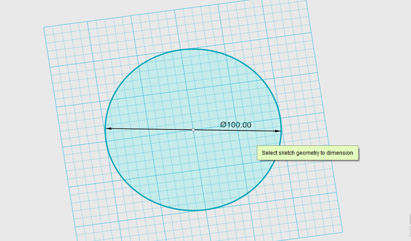
I start by selecting a circle and dragging it to the required dimensions,
I am Finding it really difficult to get the dimensions, also the colour of the background makes it difficult for the dimensions to be visible. Anyways somehow I got it done, I am starting to get a bad feeling about the software already, Ok still not judging I gave it a further go.
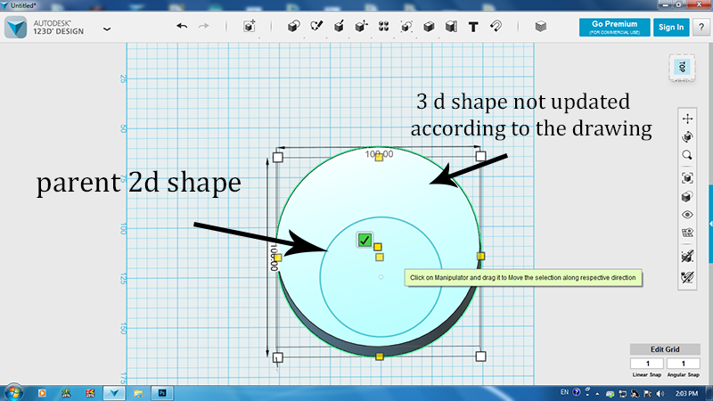
Ok After I got the required dimensions I dragged the circle from the create option on the top to make it into a cylinder, I realised that I have to reduce the size of the circle , so I went back and I did that, I was expecting that the cylinder too would reduce the diameter, but NOOOOO, it did not.
123D design is not all that parametric It should have updated the 3d shape when I changed the dimension of its parent 2d shape.
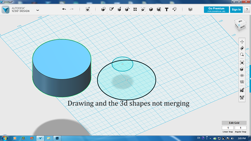
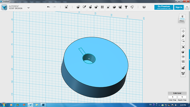
I made a drawing on the face of the cylinder to make a hole in it, I moved the cylinder from its original position to my surprise the drawing and the cylinder did not merge, This can not be the3d software of my choice I mean merging the drawing and the 3d shape on which it is drawn is a common sense, this should be the default setting, I did not even take the efforts to look into the problem, I simply stopped using it
I could reach upto here, I could not go further, not a good software, so many wrong things with it.
Fusion 360
I have heard a lot of good things about this one, It has all the rendering and simulation plugins in it. I started from where I left.
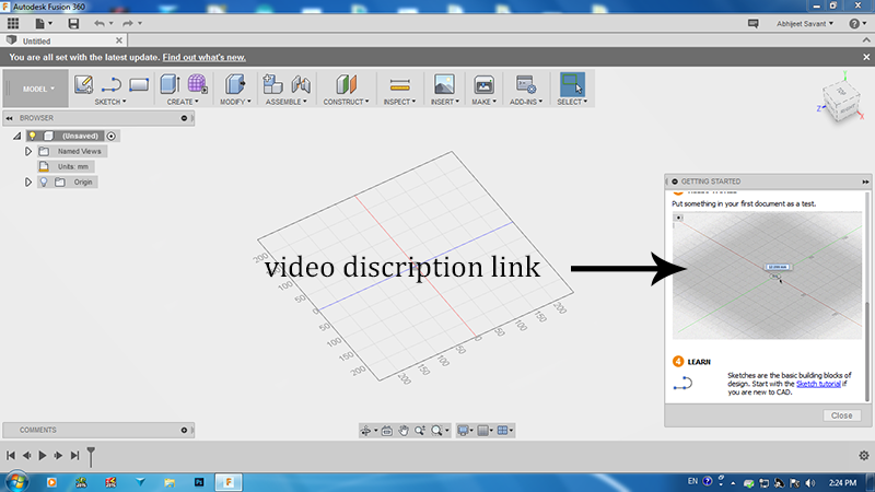
The layout is the same as 123d design but with a lot of assisting tools, the tabs and the keys are self explanatory. One good thing about the software is the video option, you have video discription of most of the functions and how to get started
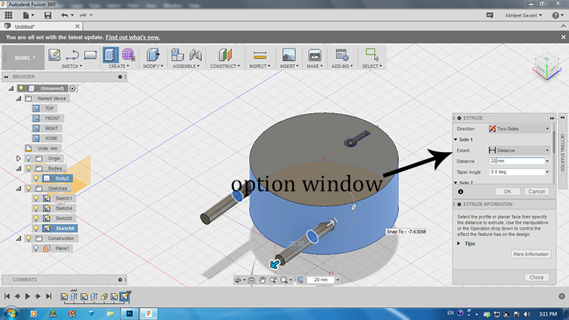
I drew a circle of the required dimensions and then I extruded it, when I click extrude I get an option window on the right hand side discribing all its functions
Great thing about Fusion360 is that it has shortcut keys for common functions such as dimensions, line, full screen, zoom in or out etc.
Some more hotkeys for Fusion 360 can be found here
I used basic functios uch as extrude, extrude cut, loft, sweep and got the final result, I also embossed a text on the object just to give it a try
There are standard funtions in this, A lot of online tutorials are available.
I have tried a lot of softwares by now, and I realized that Solidworks suits best for me it has everything, sketching, features, analysis, animation,simuation in a single package.
Design, Render, Animate, Simulate the final project
For my Final project I am doing a dome made out of natural composite material. And I am going to design and Animate the same also there is motion sensor light that I am woring on for the dome, I will design and render the same for this assignment.
Solidworks Workspace has 3 planes to work, sketching, surface, 3D modelling and rendering isplaced in the same window. The icons are self explanatory and you get a note below the icon when you hover.
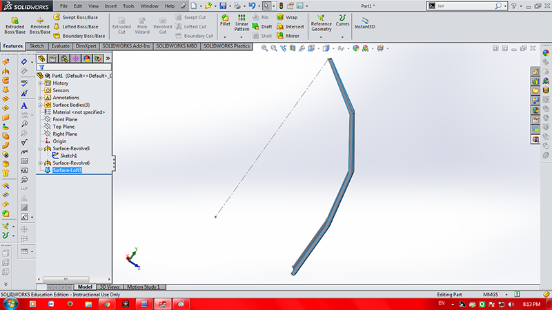
I wanted to generate an individual panel of my dome to see it in a 3D format and also see how its going to attach to the adjacent panels so I started with dimensioning and sketching.
Then I turned to SURFACE panel of solid works. In surface panel I used the command Loft Surface to generate a 3D surface of the geometry.
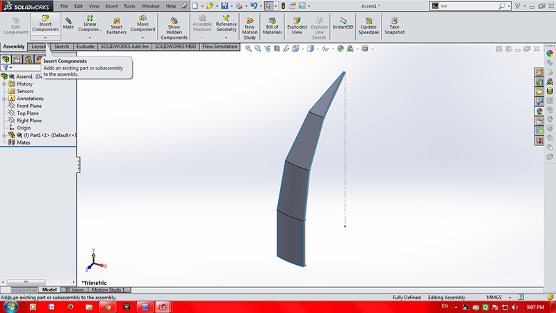
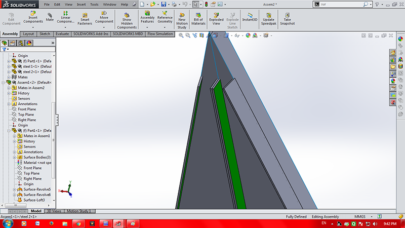
After a little tweaking I wanted to make assembly of the objects. I wanted my Panels to have steel angles at the edges to be bolted to the adjacent Panel.
I started by making a new file and selecting ASSEMBLY this time. In the assembly workspace I inserted the required components to be assembled.
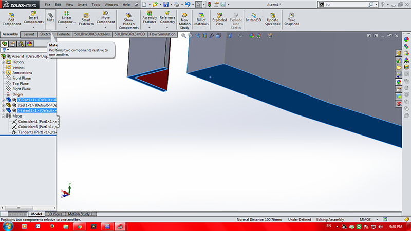
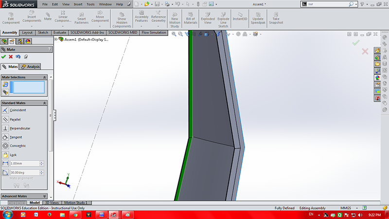
Here we have to mate the two components so that they get attachec to each other. We have several types of mates in solidworks such as geometrical mates, mechanical mates, general type of mates. The image shows a COINCIDENT MATE which falls under GENERAL MATE category.
The panel after mating all the required components looks like this. It has all the components fixed in position, inorder to move or remove the component one has to delete the corresponding Mate
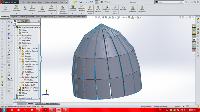
Now its time to see how my panels are going to fix to each other, I did I same thing as before, I opened a NEW FILE and selected ASSEMBLY. This time I inserted the two assemblies which we designed before. I selected the surfaces which will be bolted together and MATE them. After mating the two panels looks something like this.
I followed the same procedure for the rest of the panels after a few operations of mating and adjustin my Dome is Finally taking shape.
I also animated the way in which the two panels will be joined together in solidworks,I followed this amazing tutorial on youtube here is the link
Here is the animation I made, it is still at a novice stage
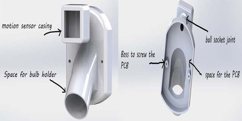
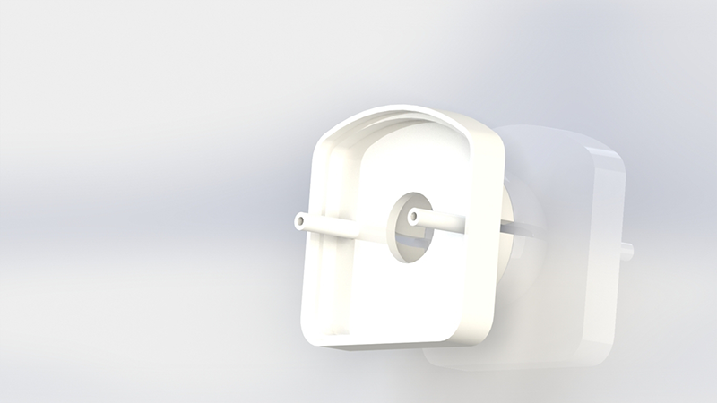
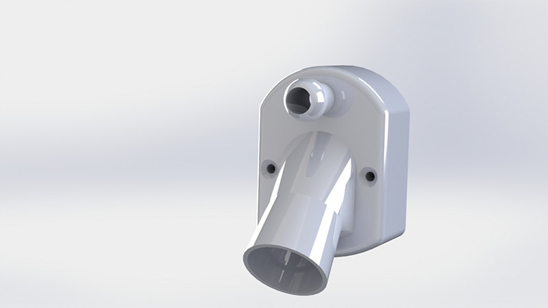
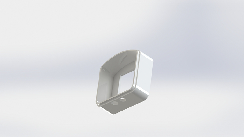
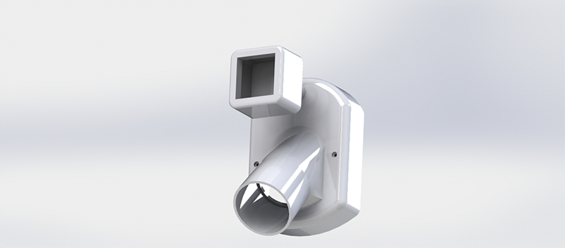
I also designed an enclosure for the motion sensing light, I gave it a plastic look and rendered it.The design consist of motion sensing light which will hold a PCB,bulb sockets and a motion sensor. Also it will have a motion sensor at the top which will have a freedom to rotate a few degrees.
I started with the normal bulb socket available in the market. I was inspired by its geometry. I extruded the casing a bit more to accomodate the PCB. I discussed with my instructor who is good in electronics design, he gave me a tentative dimensions of the PCB. Thus I designed the casing around it
First of all I will simply loved Solidworks, It is very easy to get used to the only flaw I found was that it was not an open source software. Great thing about it is that software is parametric, that means that if you edit a drawing in the parts file it will automatically update it in the assembly file.
I can go on an on for solidworks, I think I will stick to Solidworks for 2d and 3d designing
The files made in Solidworks can be converted to any format such .STEP or .STL for 3d printing and .dwg/.dxf for laser cutting
I did not like Autodesk 123d Design atall, its too basic, not parametric and the user interface is a clutter
I would like to use Fusion 360 in the future, its just like solidworks but with different names for the same functions. Good thing about Fusion 360 is that there a lot of other programs which could use the files generated by Fusion 360 such as Autodesk Meshmixer or Auto desk 123d make
Photoshop is must for me as long as I am doing fabacademy, I can edit the image in lot of ways and alo use it to reduce the file size. Photoshop icon will always be there on my Desktop
Auto cad...... I would rather not use it, even though it is a fine 2d designing software, I would stick to Solidworks instead
Same thing with Inkscape, great software especially the clone functions but I would rather stick to one environment.
Stuff I did for my Final project
I designed, rendered and animated my final project in this assignment, I made a few animation videos which will be included in my final project presentation
I made the design of motion sensing switch in this assignment, this will be used in the 3d printing assignment.


